APXVB4LTY16AB_43-C-I20
Product no: 675
|
|
|
|
|
|
|
![]()
APXVB4LTY16AB_43-C-I20
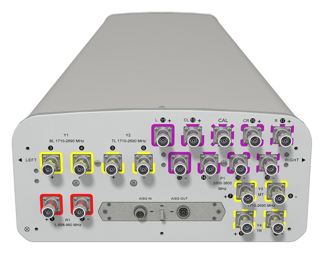
Hybrid FDD/TDD Antenna, X-Pol, 1.6m, 10-ports FDD 1x 698-960/4x 1710-2690, 65deg, 8T8R 3300-3800MHz, 90deg unit beam, Integrated RET
|
ELECTRICAL SPECIFICATIONS
|
|
Electrical Specification Header |
|
Low Band Array (698-960 MHz) [R1] |
|
Frequency Band |
MHz |
698-806 |
790-894 |
880-960 |
|
Gain Typical |
dBi |
14.1 |
14.9 |
15.3 |
|
Gain Over all Tilts |
dBi |
13.6 +/- 0.5 |
14.4 +/- 0.5 |
14.8 +/- 0.5 |
|
Azimuth Beamwidth 3dB |
Deg |
66.8 +/- 3.4 |
68.4 +/- 3 |
66.4 +/- 4.3 |
|
Elevation Beamwidth 3dB |
Deg |
16 +/- 1.5 |
13.5 +/- 0.8 |
12.8 +/- 1 |
|
Cross Polar Discrimination at Boresight |
dB |
18.8 |
22 |
22 |
|
Cross Polar Discrimination over Sector |
dB |
3.6 |
6.8 |
8 |
|
F/B at +/-30deg Total Power |
dB |
17.9 |
20.5 |
21 |
|
First Upper Side Lobe Suppression |
dB |
15.8 |
13 |
13 |
|
Electrical Downtilt |
Deg |
2 to 14 |
|
Cross Polar Isolation |
dB |
25 |
|
Interband Isolation |
dB |
25 |
|
VSWR |
- |
1.5 |
|
Passive Intermodulation (3rd Order, 2 x 43dBm) |
dBc |
-150 |
|
Maximum Effective Power per Port |
Watt |
350 |
|
|
ELECTRICAL SPECIFICATIONS
|
|
Electrical Specification Header |
|
High Band Array (1710-2690 MHz) [Y1] |
|
Frequency Band |
MHz |
1710 - 1880 |
1850 - 1990 |
1920 - 2170 |
2300 - 2400 |
2490 - 2690 |
|
Gain Typical |
dBi |
13.8 |
14 |
15 |
15.3 |
15.8 |
|
Gain Over all Tilts |
dBi |
13.3 +/- 0.5 |
13.5 +/- 0.5 |
14 +/- 1 |
14.6 +/- 0.7 |
14.8 +/- 1 |
|
Azimuth Beamwidth 3dB |
Deg |
68.9 +/- 6.8 |
64.8 +/- 6.7 |
63.8 +/- 6.7 |
56.5 +/- 4.6 |
53.4 +/- 6.2 |
|
Elevation Beamwidth 3dB |
Deg |
12 +/- 2 |
11.1 +/- 1 |
10.1 +/- 1 |
9.4 +/- 0.6 |
8.7 +/- 0.5 |
|
Cross Polar Discrimination at Boresight |
dB |
16.4 |
18 |
17 |
16 |
14 |
|
Cross Polar Discrimination over Sector |
dB |
6.9 |
9 |
6 |
1 |
0.1 |
|
F/B at +/-30deg Total Power |
dB |
16.9 |
17.6 |
18 |
18.4 |
19 |
|
First Upper Side Lobe Suppression |
dB |
15 |
13 |
11 |
9.7 |
7 |
|
Electrical Downtilt |
Deg |
2 to 12 |
|
Cross Polar Isolation |
dB |
25 |
|
Interband Isolation |
dB |
25 |
|
VSWR |
- |
1.5 |
|
Passive Intermodulation (3rd Order, 2 x 43dBm) |
dBc |
-150 |
|
Maximum Effective Power per Port |
Watt |
250 |
|
|
ELECTRICAL SPECIFICATIONS
|
|
Electrical Specification Header |
|
High Band Array (1710-2690 MHz) [Y2] |
|
Frequency Band |
MHz |
1710-1880 |
1850-1990 |
1920-2170 |
2300-2400 |
2490-2690 |
|
Gain Typical |
dBi |
13.4 |
13.9 |
15.3 |
15.8 |
16 |
|
Gain Over all Tilts |
dBi |
12.7 +/- 0.7 |
12.9 +/- 1 |
13.8 +/- 1.5 |
14.8 +/- 1 |
15 +/- 1 |
|
Azimuth Beamwidth 3dB |
Deg |
66.3 +/- 7.2 |
66.5 +/- 6.3 |
66 +/- 5.4 |
54 +/- 3.7 |
50.5 +/- 4.5 |
|
Elevation Beamwidth 3dB |
Deg |
12.1 +/- 1 |
11.7 +/- 1 |
10.8 +/- 1 |
9.3 +/- 0.5 |
8.7 +/- 0.5 |
|
Cross Polar Discrimination at Boresight |
dB |
19 |
19 |
14.3 |
13.8 |
12.4 |
|
Cross Polar Discrimination over Sector |
dB |
7 |
8 |
9 |
1 |
1 |
|
F/B at +/-30deg Total Power |
dB |
18 |
16 |
16.8 |
17.9 |
18 |
|
First Upper Side Lobe Suppression |
dB |
11 |
13.8 |
12 |
13 |
12 |
|
Electrical Downtilt |
Deg |
2 to 12 |
|
Cross Polar Isolation |
dB |
25 |
|
Interband Isolation |
dB |
25 |
|
VSWR |
- |
1.5 |
|
Passive Intermodulation (3rd Order, 2 x 43dBm) |
dBc |
-150 |
|
Maximum Effective Power per Port |
Watt |
250 |
|
|
ELECTRICAL SPECIFICATIONS
|
|
Electrical Specification Header |
|
High Band Array (1710-2690 MHz) [Y3] |
|
Frequency Band |
MHz |
1710-1880 |
1850-1990 |
1920-2170 |
2300-2400 |
2490-2690 |
|
Gain Typical |
dBi |
14.8 |
14.9 |
15.9 |
15.1 |
16.1 |
|
Gain Over all Tilts |
dBi |
13.8 +/- 1 |
14.3 +/- 0.6 |
14.9 +/- 1 |
14.6 +/- 0.5 |
14.8 +/- 1.3 |
|
Azimuth Beamwidth 3dB |
Deg |
68.5 +/- 5.7 |
66.7 +/- 4 |
62.3 +/- 6.5 |
60.6 +/- 2.5 |
54.8 +/- 4.5 |
|
Elevation Beamwidth 3dB |
Deg |
13.3 +/- 1 |
12.6 +/- 0.5 |
11.7 +/- 1 |
10.5 +/- 0.5 |
9.8 +/- 1 |
|
Cross Polar Discrimination at Boresight |
dB |
19.1 |
19.1 |
19 |
24.8 |
20.8 |
|
Cross Polar Discrimination over Sector |
dB |
9 |
8.5 |
7 |
7 |
2.1 |
|
F/B at +/-30deg Total Power |
dB |
21 |
20 |
20 |
19.7 |
21 |
|
First Upper Side Lobe Suppression |
dB |
13.6 |
14.9 |
14 |
14.9 |
14 |
|
Electrical Downtilt |
Deg |
2 to 12 |
|
Cross Polar Isolation |
dB |
25 |
|
Interband Isolation |
dB |
25 |
|
VSWR |
- |
1.5 |
|
Passive Intermodulation (3rd Order, 2 x 43dBm) |
dBc |
-150 |
|
Maximum Effective Power per Port |
Watt |
250 |
|
|
ELECTRICAL SPECIFICATIONS
|
|
Electrical Specification Header |
|
High Band Array (1710-2690 MHz) [Y4] |
|
Frequency Band |
MHz |
1710-1880 |
1850-1990 |
1920-2170 |
2300-2400 |
2490-2690 |
|
Gain Typical |
dBi |
14.4 |
14.9 |
16.1 |
15.8 |
15.9 |
|
Gain Over all Tilts |
dBi |
13.9 +/- 0.5 |
14.4 +/- 0.5 |
15.1 +/- 1 |
14.9 +/- 0.9 |
14.9 +/- 1 |
|
Azimuth Beamwidth 3dB |
Deg |
73.1 +/- 4.1 |
69.3 +/- 3.5 |
65.6 +/- 4 |
58.6 +/- 3.5 |
56.4 +/- 3.5 |
|
Elevation Beamwidth 3dB |
Deg |
13.2 +/- 1 |
12.6 +/- 0.5 |
11.9 +/- 1 |
10.5 +/- 0.5 |
9.6 +/- 0.7 |
|
Cross Polar Discrimination at Boresight |
dB |
19.7 |
22.9 |
20 |
18.6 |
20.4 |
|
Cross Polar Discrimination over Sector |
dB |
11 |
12 |
13 |
6.7 |
2 |
|
F/B at +/-30deg Total Power |
dB |
22.4 |
22.4 |
22 |
20 |
21 |
|
First Upper Side Lobe Suppression |
dB |
13 |
13.6 |
12.1 |
14.4 |
13 |
|
Electrical Downtilt |
Deg |
2 to 12 |
|
Cross Polar Isolation |
dB |
25 |
|
Interband Isolation |
dB |
25 |
|
VSWR |
- |
1.5 |
|
Passive Intermodulation (3rd Order, 2 x 43dBm) |
dBc |
-150 |
|
Maximum Effective Power per Port |
Watt |
250 |
|
|
ELECTRICAL SPECIFICATIONS
|
|
Electrical Specification Header |
|
Cal. board and S parameter (3300-3800 MHz) [P1] |
|
Frequency Band |
MHz |
3300-3600 |
3600-3800 |
|
Coupling between cal. Port to input port |
dB |
-26+/-2 |
|
Coupling amplitude accuracy |
dB |
≤ 0.9 |
|
Coupling phase accuracy |
deg |
≤ 7 |
|
VSWR |
- |
≤ 1.5 |
|
Maximum Power |
Watt |
50 |
|
ISO co-polor @ 2-6 deg tilt |
dB |
≥ 19 |
|
ISO co-polor @ 7-12 deg tilt |
dB |
≥ 25 |
|
ISO cross-polor @ 2-6 deg tilt |
dB |
≥ 24 |
|
ISO cross-polor @ 7-12 deg tilt |
dB |
≥ 25 |
|
|
ELECTRICAL SPECIFICATIONS
|
|
Electrical Specification Header |
|
Radiation Parameter - Unit Beam (3300-3800 MHz) [P1] |
|
Frequency Band |
MHz |
3300-3600 |
3600-3800 |
|
Gain Typical |
dBi |
15.2 |
15.3 |
|
Gain Over all Tilts |
dBi |
14.7 +/- 0.5 |
14.8 +/- 0.5 |
|
Azimuth Beamwidth 3dB |
Deg |
78.4 +/- 7.4 |
70.8 +/- 4.6 |
|
Elevation Beamwidth 3dB |
Deg |
7 +/- 1 |
6.6 +/- 0.5 |
|
Cross Polar Discrimination at Boresight |
dB |
20.9 |
19.9 |
|
Cross Polar Discrimination over Sector |
dB |
12 |
13 |
|
F/B at +/-30deg Total Power |
dB |
19 |
21 |
|
First Upper Side Lobe Suppression |
dB |
16 |
16.8 |
|
Electrical Downtilt |
Deg |
2 to 12 |
|
VSWR |
- |
1.5 |
|
|
ELECTRICAL SPECIFICATIONS
|
|
Electrical Specification Header |
|
Radiation Parameter - Broad casting Beam (3300-3800 MHz) [P1] |
|
Frequency Band |
MHz |
3300-3600 |
3600-3800 |
|
Gain Typical |
dBi |
16.4 |
16.4 |
|
Gain Over all Tilts |
dBi |
15.4 +/- 1 |
15.4 +/- 1 |
|
Azimuth Beamwidth 3dB |
Deg |
61.5 +/- 7.7 |
59 +/- 7.8 |
|
Elevation Beamwidth 3dB |
Deg |
7 +/- 1 |
6.7 +/- 0.5 |
|
F/B at +/-30deg Total Power |
dB |
21.9 |
20.8 |
|
First Upper Side Lobe Suppression |
dB |
16 |
15.4 |
|
Electrical Downtilt |
Deg |
2 to 12 |
|
VSWR |
- |
1.5 |
|
|
ELECTRICAL SPECIFICATIONS
|
|
Electrical Specification Header |
|
Radiation Parameter - Working Beam (3300-3800 MHz) [P1] |
|
Frequency Band |
MHz |
3300-3600 |
3600-3800 |
|
Gain Typical |
dBi |
21 |
20.7 |
|
Gain Over all Tilts |
dBi |
20.5 +/- 0.5 |
20.2 +/- 0.5 |
|
Azimuth Beamwidth 3dB |
Deg |
21.6 +/- 0.7 |
20.4 +/- 0.6 |
|
Elevation Beamwidth 3dB |
Deg |
7 +/- 1 |
6.6 +/- 0.5 |
|
F/B at +/-30deg Total Power |
dB |
27 |
|
First Upper Side Lobe Suppression |
dB |
17 |
|
Electrical Downtilt |
Deg |
2 to 12 |
|
VSWR |
- |
1.5 |
|
|
ELECTRICAL SPECIFICATIONS
|
|
Impedance |
Ohm |
50 |
|
Polarization |
Deg |
±45° |
|
|
MECHANICAL SPECIFICATIONS
|
|
Dimensions - H x W x D |
mm (in) |
1650 x 429 x 199 (65 x 16.9 x 7.8) |
|
Weight (Antenna Only) |
kg (lb) |
28 (61.7) |
|
Weight (Mounting Hardware only) |
kg (lb) |
4.5 (9.9) |
|
Packing size- HxWxD |
mm (in) |
1920 x 525 x 295 (75.6 x 20.7 x 11.6) |
|
Shipping Weight |
kg (lb) |
39.5 (87.1) |
|
Connector type |
|
19 x 4.3-10 female bottom + 2 AISG connectors (1 male, 1 female) |
|
Radome Material / Color |
|
Fiber Glass / Light Grey RAL7035 |
|
|
TESTING AND ENVIRONMENTAL
|
|
Temperature Range |
°C (°F) |
-40 to 60 (-40 to 140 ) |
|
Lightning protection |
|
DC Ground |
|
Survival/Rated Wind Velocity |
km/h |
200 (150 ) |
|
Survival wind Velocity |
km/h |
200 |
|
|
ORDERING INFORMATION
|
|
Order No. |
Configuration |
Mounting Hardware |
Mounting pipe Diameter |
Shipping Weight |
|
APXVB4LTY16AB_43-C-I20 |
Internal RET(ACU-I20-B6) |
APM50-B1 |
50-110mm |
39.5 kg |
|
|
|
|
|
|
|
|
-
2 ports / 1 cross pol system in low band (698-960MHz)
-
8 ports / 4 cross pol systems in high band (1710-2690MHz)
-
8 ports / 4 cross pol systems in high band (3300-3800MHz)
-
Integrated and field replaceable SRET
-
ACU HW Version: 2.02
-
Compliant with AISG V2.0 and 3GPP
Other products of the same category
|